How to Ensure “Zero Emissions” During SF6 Gas Recovery and Refilling: A 2026 Technical Guide
Date
2026-03-20
[email protected]
Website
www.sf6gasdetector.com
Get Solutions And Quotes
How to Ensure “Zero Emissions” During SF6 Gas Recovery and Refilling: A 2026 Technical Guide
In the current regulatory landscape, Sulfur Hexafluoride (SF6) management has transitioned from operational maintenance to a critical environmental mandate. With the 2026 F-gas amendments now active, power utilities and industrial plants are under intense scrutiny to prove “Zero Emission” performance.
Achieving a true zero-emission workflow requires a synergy of high-precision hardware and rigorous Standard Operating Procedures (SOPs). Below is a technical analysis of how to eliminate leakage during the SF6 gas recovery and refilling cycle.
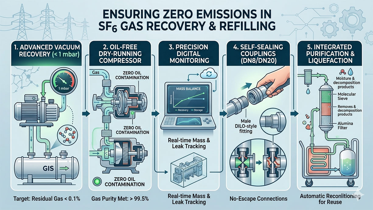
1. Advanced SF6 Gas Vacuum Recovery: The “Under 1 mbar” Standard
The most common source of “hidden” emissions is residual gas left in the Gas Insulated Switchgear (GIS) due to insufficient vacuum depth.
-
The Technical Barrier: Many standard units stop at 10–20 mbar. At these levels, up to 2% of the gas volume remains trapped in the “dead zones” of the equipment.
-
The Zero-Emission Solution: Our advanced recovery systems utilize high-performance, multi-stage vacuum pumps capable of reaching a blank-off pressure of less than 1 mbar.
-
Operational Advantage: By pulling a deeper vacuum, you ensure that 99.9% of the SF6 mass is liquefied and stored, preventing any “puff” of gas when the seals are finally broken for maintenance.
2. Eliminating Cross-Contamination with Oil-Free Technology
Traditional lubricated compressors pose a dual threat: they contaminate the SF6 gas with oil mist (rendering it non-reusable) and often suffer from micro-leaks at the piston seals.
-
Core Advantage: We utilize dry-running, oil-free compressor technology.
-
The Result: The gas remains at “as-new” purity levels (meeting IEC 60480 standards), allowing for immediate onsite refilling. This eliminates the need for off-site transport, which is a high-risk stage for accidental emissions.
3. Precision Monitoring: Digital Twin and Real-Time Mass Balance
You cannot manage what you cannot measure. In 2026, “Zero Emissions” must be backed by data for ESG auditing.
-
Technical Parameter: Integration of high-precision mass-flow meters (accuracy +/- 0.1kg).
-
Digital Integration: Our SF6 gas recovery and refilling systems utilize Digital Twin technology to monitor gas density, temperature, and pressure in real-time.
-
Scenario Analysis: During a 110kV GIS bay maintenance project, the system automatically logs the “In” and “Out” mass. If the numbers don’t balance, the system triggers an immediate leak-path alert, allowing technicians to intervene before gas escapes.
4. Leak-Free Interconnection: Self-Sealing Coupling Systems
Manual errors during hose connection and disconnection are a primary source of small-scale emissions.
-
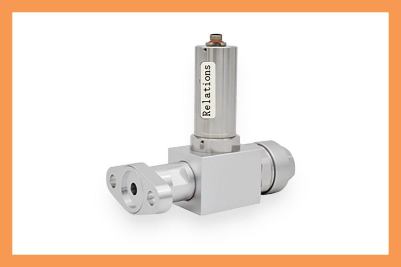
Hardware Solution: The use of DN8 and DN20 self-sealing couplings (DILO-compatible).
-
The “Zero” Factor: These valves only open when fully coupled and snap shut before the threads disengage. This prevents the “hiss” of escaping gas common in older, manual-valve systems.
5. Usage Scenario: Substation Maintenance in 2026
In high-density urban substations or offshore wind farms, the “Zero Emission” requirement is absolute due to environmental sensitivity.
-
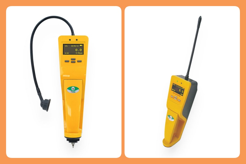
The Challenge: High wind or cramped spaces make traditional leak detection difficult.
-
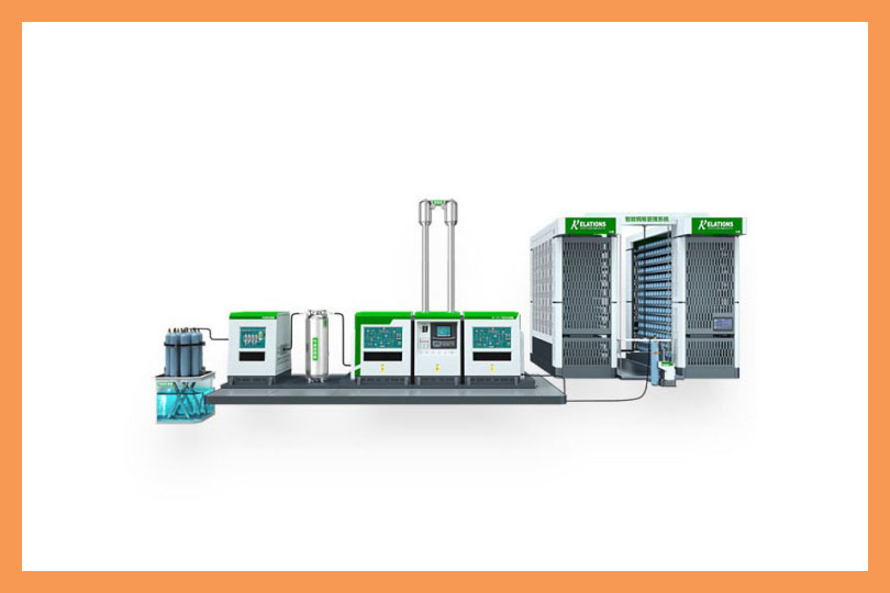
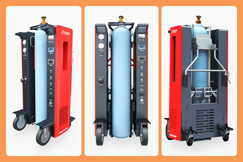
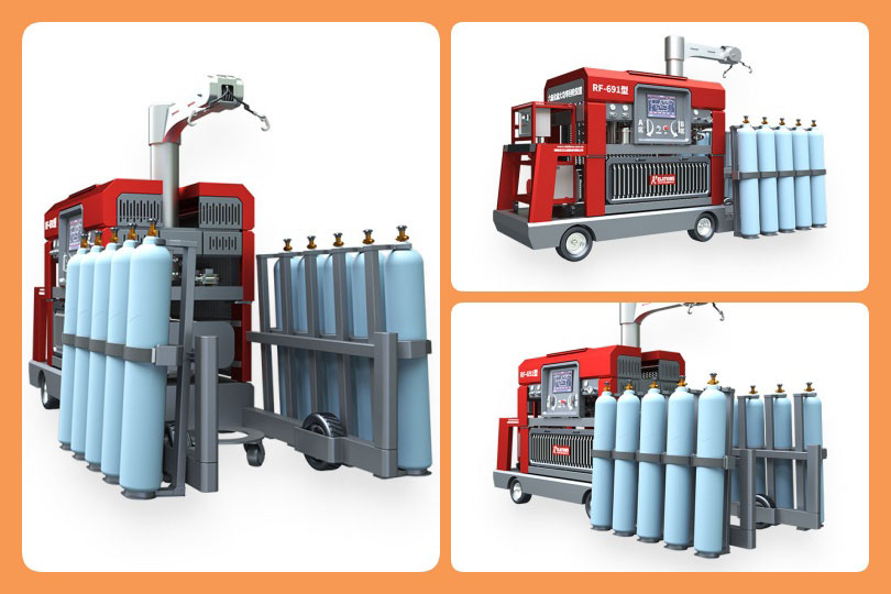
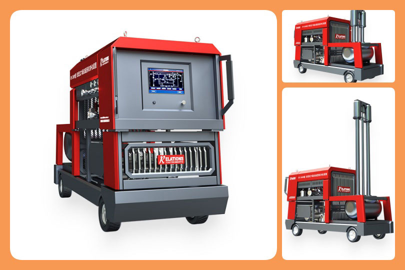
The Practicality: By using a compact, automated processing center that integrates automatic liquefaction, the gas is stored in a liquid state at high pressure, reducing the storage volume and the number of connection points (and potential leak paths) by 60%.
Summary of Technical Parameters for Compliance
| Feature | Standard Requirement | Our “Zero-Emission” Specification |
| Final Vacuum | Less than 20 mbar | Less than 1 mbar |
| Gas Purity (after recovery) | Greater than 97% | Greater than 99.5% (Purified) |
| Compressor Type | Standard | 100% Oil-Free / Dry-Running |
| Data Logging | Manual | Automated IoT Cloud Sync |
Conclusion
Ensuring “Zero Emissions” is no longer just about the skill of the technician; it is about the precision of the equipment. By investing in high-vacuum, oil-free, and digitally-monitored recovery systems, companies can protect their assets, stay compliant with 2026 regulations, and significantly reduce their carbon footprint.