How to Pinpoint SF6 Leaks in a Metal-Clad GIS Compartment Step by Step
Date
2026-07-20
[email protected]
Website
www.sf6gasdetector.com
Get Solutions And Quotes
How to Pinpoint SF6 Leaks in a Metal-Clad GIS Compartment Step by Step
How Do You Pinpoint an SF6 Leak Inside a Metal-Clad GIS Compartment Step by Step?
Sulfur hexafluoride (SF6) is widely used in gas-insulated switchgear because of its excellent dielectric strength and arc-quenching performance. However, when a leak occurs inside a metal-clad GIS compartment, it can reduce insulation reliability, compromise operational safety, and increase environmental compliance risks. Accurate SF6 leak detection requires a structured method, the right SF6 gas leak detector, and a clear understanding of GIS compartment design, gas pressure behavior, and SF6 dew point conditions.
This guide explains how to pinpoint an SF6 leak inside a metal-clad GIS compartment step by step, covering practical inspection procedures, equipment selection, key parameters, application scenarios, and purchasing considerations for industrial users.
Why SF6 Leak Detection Matters in Metal-Clad GIS Compartments
A metal-clad GIS compartment is designed to provide compact, sealed, and highly reliable insulation for high-voltage equipment. Since SF6 is enclosed within sealed compartments, even a small leakage point may remain hidden until pressure drops, alarms activate, or insulation performance is affected.
Professional SF6 leak detection helps operators:
- Maintain safe dielectric insulation performance
- Reduce unplanned shutdowns and maintenance costs
- Meet environmental and regulatory requirements for SF6 emissions
- Protect personnel from gas accumulation in confined spaces
- Identify sealing defects before they become major failures
- Verify equipment integrity after installation, overhaul, or gas refilling
In addition to leak concentration, engineers often evaluate SF6 dew point because moisture in SF6 gas can affect insulation performance and contribute to decomposition by-products during arcing or partial discharge events.
Core Advantages of Using a Professional SF6 Gas Leak Detector
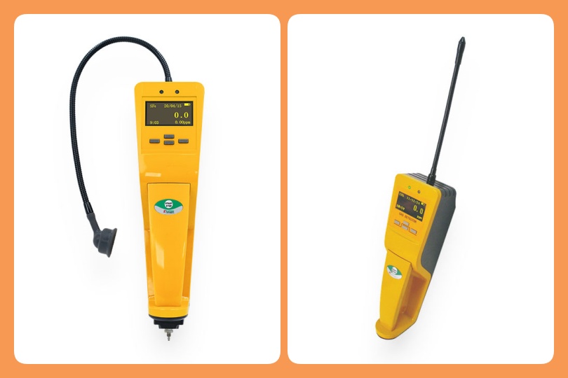
A high-quality SF6 gas leak detector is essential for precise leak localization in GIS bays, cable sealing ends, flange joints, density relay connections, and inspection ports. Compared with basic gas monitoring methods, professional leak detectors provide faster response, higher sensitivity, and better reliability in industrial environments.
Key Benefits
- High sensitivity: Detects small leakage rates before major gas loss occurs.
- Fast response time: Allows technicians to scan multiple sealing points efficiently.
- Portable operation: Suitable for substations, GIS rooms, production workshops, and field maintenance.
- Selective detection: Reduces interference from other gases when using dedicated SF6 sensing technology.
- Data support: Some models support concentration logging, alarm records, and maintenance traceability.
- Improved safety: Helps technicians locate leaks without unnecessary disassembly.
For site-specific recommendations on detector sensitivity, probe type, and inspection workflow, industrial users can request a free technical consultation via [email protected].
Step-by-Step Process to Pinpoint an SF6 Leak Inside a Metal-Clad GIS Compartment
Step 1: Review GIS Documentation and Safety Requirements
Before starting SF6 leak detection, review the GIS layout drawings, gas compartment diagram, nameplate pressure values, density relay settings, and historical maintenance records. Identify all possible leakage points, including:
- Flange joints
- Gas filling valves
- Density monitor connections
- Inspection covers
- Bushings and cable terminations
- Expansion joints
- Sealing gaskets
- Welded seams and bolted interfaces
Ensure that all work complies with site electrical safety procedures, lockout/tagout requirements, confined-space rules where applicable, and local SF6 environmental handling regulations. Technicians should wear appropriate PPE and confirm that the GIS operating condition permits inspection.
Step 2: Check Gas Pressure, Alarm Records, and SF6 Dew Point
Before using an SF6 gas leak detector, verify whether the compartment pressure or density has changed abnormally. Compare current readings with historical values corrected for temperature.
Measure or review the SF6 dew point if moisture contamination is suspected. A rising dew point may indicate improper gas handling, aging seals, moisture ingress, or poor maintenance practices. Although SF6 dew point testing does not directly locate a leak, it provides valuable diagnostic information about internal gas quality.
Step 3: Prepare the SF6 Gas Leak Detector
Turn on the detector in a clean-air environment and allow it to warm up according to the manufacturer’s instructions. Confirm calibration status, battery level, alarm threshold, and probe condition.
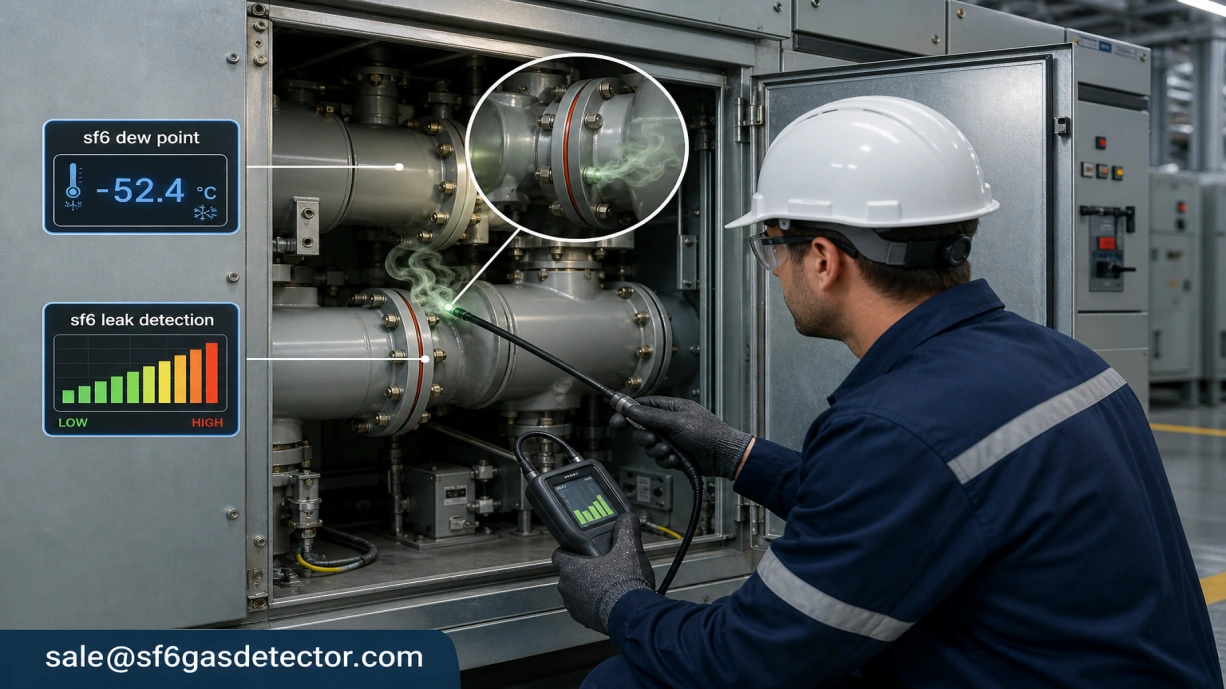
For GIS leak pinpointing, a flexible probe is often useful because leakage points are commonly located around narrow flange gaps, valve interfaces, and recessed bolts. If the detector includes sensitivity levels, begin with a higher sensitivity mode for screening, then reduce sensitivity when narrowing down the exact leak source.
Step 4: Perform a Slow and Systematic External Scan
Move the probe slowly around each suspected leakage point. Keep the probe tip close to the surface without blocking airflow. A recommended scanning speed is typically slow enough to allow the sensor to respond to small gas concentrations.
Focus on one area at a time. Start from the upper part of the metal-clad GIS compartment and gradually inspect downward, because airflow, ventilation, and enclosure geometry may affect gas dispersion. Pay special attention to gasket lines, flange surfaces, pressure relief devices, density monitor tubing, and gas valve caps.
Step 5: Confirm the Leak Signal
When the SF6 gas leak detector alarms, do not immediately assume the first alarm point is the actual leakage source. SF6 may drift from another point due to air movement. Repeat the measurement by approaching the suspected area from multiple directions.
A real leak usually produces a repeatable signal at the same location. To confirm, move the probe away until the reading drops, then return slowly to the suspected point. If the alarm rises consistently at the same sealing interface, the leak source is likely nearby.
Step 6: Isolate the Exact Leakage Point
After identifying the suspect zone, reduce detector sensitivity if needed and inspect smaller sections of the component. For example, if a flange area triggers an alarm, scan around the full circumference to determine whether the leak comes from one bolt position, a gasket section, or an adjacent valve fitting.
Technicians may use temporary shielding from ventilation airflow to improve detection stability. However, avoid sealing or covering components in a way that creates unsafe pressure or heat conditions.
Step 7: Record Findings and Plan Corrective Action
Document the leakage location, detector reading, environmental conditions, gas pressure, SF6 dew point data if available, and inspection time. Photos and marked diagrams are useful for maintenance planning.
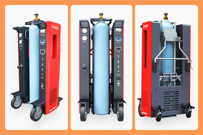
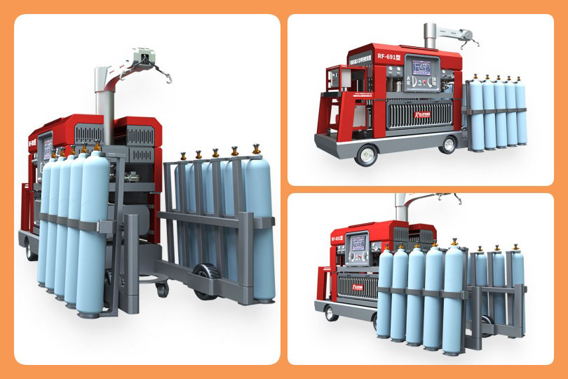
Corrective actions may include tightening approved fittings to specified torque, replacing valve caps or seals, repairing gasket interfaces, or scheduling compartment shutdown for internal maintenance. Any gas recovery, refilling, or treatment should follow approved SF6 handling procedures and environmental regulations.
Typical Technical Parameters for SF6 Leak Detection Equipment
| Parameter | Recommended Range or Feature | Practical Importance |
|---|---|---|
| Target gas | SF6 | Ensures selective detection for GIS applications |
| Sensitivity | ppm-level or leak-rate equivalent | Helps identify small leaks early |
| Response time | Fast response, typically seconds | Improves field inspection efficiency |
| Probe type | Flexible or handheld probe | Allows access to narrow GIS areas |
| Alarm mode | Audible, visual, vibration optional | Supports noisy substation environments |
| Portability | Battery-powered handheld design | Suitable for field and indoor GIS rooms |
| Calibration | Factory or periodic calibration support | Ensures measurement reliability |
| Data logging | Optional | Useful for maintenance records and audits |
| Operating environment | Industrial temperature and humidity range | Required for substation reliability |
Key Application Scenarios
GIS Substation Maintenance
Routine SF6 leak detection is commonly performed during scheduled maintenance, annual inspections, and after alarm events. It helps utilities maintain equipment reliability and reduce SF6 emissions.
Factory Acceptance and Site Acceptance Testing
Manufacturers and EPC contractors use SF6 gas leak detector equipment during FAT and SAT procedures to verify sealing quality before energization.
Emergency Pressure Drop Investigation
If a metal-clad GIS compartment experiences abnormal density relay alarms, leak detection helps quickly identify whether the issue is caused by actual leakage, temperature compensation error, or instrumentation failure.
Gas Quality and Moisture Investigation
When SF6 dew point readings are abnormal, technicians may conduct leak detection to evaluate whether moisture ingress is related to compromised sealing points.
For customized on-site GIS inspection plans and detector configuration advice, contact the engineering team at [email protected].
Purchasing Guide: How to Choose the Right SF6 Gas Leak Detector
Match Sensitivity to Your GIS Risk Level
High-voltage GIS assets require early leak identification. Choose a detector with sensitivity suitable for small leaks around flanges, valves, and instrument connections.
Consider Probe Accessibility
Metal-clad GIS compartments often include compact structures and hard-to-reach points. A flexible probe, extension tube, or slim sensing head improves practical usability.
Verify Calibration and Traceability
For professional maintenance programs, calibration support is essential. Select equipment that provides stable readings and documented calibration options.
Evaluate Field Durability
Substation environments may involve dust, humidity, electromagnetic interference, and temperature variation. Choose an industrial-grade device designed for field use.
Look for Technical Support
Beyond hardware, reliable supplier support matters. Training, application guidance, and troubleshooting assistance can significantly improve inspection accuracy. For one-on-one engineer guidance before purchasing, users may email [email protected].
Frequently Asked Questions
Can SF6 dew point testing locate a leak?
No. SF6 dew point testing measures moisture content in the gas and helps evaluate gas quality. It does not directly pinpoint leakage locations. However, abnormal dew point values may indicate sealing problems or improper gas handling, which should be followed by SF6 leak detection.
Where do SF6 leaks most commonly occur in a metal-clad GIS compartment?
Common leakage points include flange gaskets, filling valves, density relay connections, pressure relief devices, cable termination interfaces, and inspection covers. Leaks can also occur at aging seals or improperly tightened fittings.
How often should SF6 leak detection be performed?
Inspection frequency depends on asset criticality, local regulations, manufacturer recommendations, and maintenance history. Many operators include leak checks during routine maintenance, after gas filling, after major repairs, and whenever density alarms or pressure drops occur.
Is it safe to inspect an energized GIS compartment?
External SF6 leak detection may be performed on energized equipment only if site safety procedures permit it and qualified personnel follow electrical safety distances and operational rules. Internal maintenance requires proper isolation, gas recovery, and lockout/tagout procedures.
What should be done after a leak is found?
Record the leak location, confirm the signal, evaluate gas pressure and gas quality, then plan corrective maintenance. Do not release SF6 intentionally. Gas recovery and refilling should be conducted using approved SF6 handling equipment and compliant procedures.
Conclusion
Pinpointing an SF6 leak inside a metal-clad GIS compartment requires a disciplined, step-by-step approach: review documentation, verify pressure and SF6 dew point data, prepare the SF6 gas leak detector, scan systematically, confirm repeatable signals, isolate the exact leakage point, and document corrective actions. With professional SF6 leak detection practices and the right detector, utilities, manufacturers, and maintenance teams can improve GIS reliability, reduce environmental impact, and maintain compliance with industrial safety and operational standards.