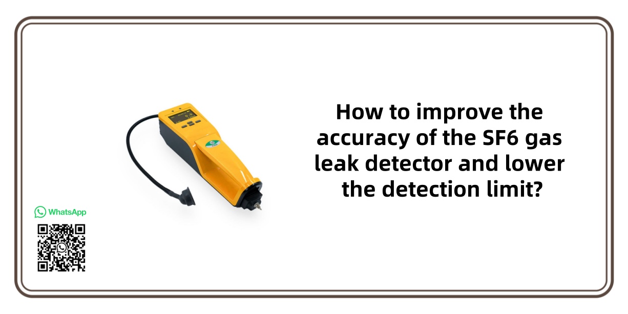
How to improve the accuracy of the SF6 gas leak detector and lower the detection limit?
Date
2025-07-01
sale@sf6gasdetector.com
Website
www.sf6gasdetector.com
Get Solutions And Quotes
How to improve the accuracy of the SF6 gas leak detector and lower the detection limit?
Improving the accuracy of the SF6 gas leak detector (reducing measurement errors) and lowering the detection limit (enhancing trace detection capabilities) is a systematic project that requires optimization from multiple dimensions such as sensor technology, signal processing, calibration systems, and environmental control. The core is to reduce noise interference, improve signal sensitivity, and enhance measurement stability. The following are the specific technical paths and implementation methods:
1. Upgrade the core sensor technology: Improve signal sensitivity and selectivity
The sensor is the “source” of detection accuracy and limit, and its performance directly determines the basic capabilities of the SF6 gas leak detector. It needs to be optimized in terms of sensitivity, anti – interference ability, and stability:
Adopt highly sensitive detection principles
Traditional SF6 detectors are mostly based on the infrared absorption method (SF6 has a strong absorption in the 10.6μm band), but the sensitivity is limited (the detection limit is usually ≥ 1ppm). It can be upgraded to more sensitive technologies:
Laser spectroscopy technology (such as TDLAS, Tunable Diode Laser Absorption Spectroscopy): By precisely locking the characteristic absorption peak of SF6 with a narrow – linewidth laser, it has strong anti – interference ability, high signal – to – noise ratio, the detection limit can be reduced to the 0.01ppm level, and the linear range is wide (the accuracy can still be maintained within ± 2% at low concentrations).
Photoacoustic spectroscopy technology (PAS): Utilizes the acoustic signal generated after SF6 absorbs light of a specific wavelength (proportional to the concentration), avoiding the light intensity fluctuation interference of the infrared method. The sensitivity is 1 – 2 orders of magnitude higher than that of traditional infrared, making it suitable for ultra – trace detection (the limit can reach 0.001ppm).
Optimize the sensor structure and materials
Gas cell design of infrared/laser sensors: Use a long – optical – path gas cell (such as a multi – reflection gas cell with an optical path of more than 10 meters), increase the interaction time between SF6 molecules and light, and enhance the signal intensity (the signal is proportional to the optical path), thereby reducing the detection limit.
Reduce the “dark current” or “background noise” of the sensor: For example, select a cryogenic refrigeration type for the infrared detector (such as a mercury cadmium telluride detector) to reduce thermal noise; use phase – locked loop technology in the laser sensor to stabilize the laser frequency and reduce drift noise.
2. Strengthen signal processing and algorithms: Suppress noise and extract effective signals
Even if the sensor outputs a weak signal, by optimizing the signal processing process, the signal – to – noise ratio (S/N) can be significantly improved, thereby reducing the detection limit and improving accuracy. The core is “noise reduction” and “signal amplification”:
High – precision signal amplification and filtering
Use a low – noise operational amplifier (such as an instrumentation amplifier) to amplify the weak electrical signal (μV level) output by the sensor to the processable mV level, while avoiding introducing the amplifier’s own noise.
Multistage filtering technology:
Hardware filtering: Filter out environmental electromagnetic interference (such as 50Hz power frequency noise) and high – frequency random noise through RC low – pass filtering and band – pass filtering;
Digital filtering: Further smooth the signal fluctuations through software algorithms (such as Kalman filtering, moving average filtering) to reduce instantaneous interference (such as signal jumps caused by air flow disturbances).
Lock – in amplification technology (Lock – in Amplification)
Modulate the light source (such as modulating the laser intensity with a sine wave), so that the signal generated by SF6 carries specific frequency information. Then, through a lock – in amplifier, only the signal of this frequency is extracted, completely shielding the background noise of non – modulated frequencies (such as ambient light, circuit noise). This technology can increase the signal – to – noise ratio by 100 – 1000 times and is a key means to reduce the detection limit (especially suitable for sub – ppm detection).
Non – linear correction algorithm
The sensor may have a non – linear response in the low – concentration region (such as the infrared absorption deviating from the Lambert – Beer law at high concentrations). Through software algorithms (such as polynomial fitting, neural network correction), linearize the measurement curve to ensure that the measured value is consistent with the true concentration across the full range (especially near the detection limit), improving the accuracy of the SF6 gas leak detector.
3. Optimize the calibration and traceability system: Reduce systematic errors
The core of accuracy is “the consistency between the measured value and the true value”, and scientific calibration methods are needed to eliminate systematic deviations, especially in the low – concentration region:
High – precision standard gas calibration
Use SF6 standard gases traceable to the national metrology institute (with a concentration uncertainty of ≤ 1%), covering multiple concentration points from the detection limit to the full scale (such as 0.01ppm, 0.1ppm, 1ppm, 10ppm), rather than just single – point calibration.
Focus on low – concentration calibration: For the area near the detection limit (such as 0.01 – 0.1ppm), a “zero gas + trace standard gas” mixing system (dynamic gas mixer) is required to accurately prepare low – concentration standard gases, avoiding concentration deviations caused by adsorption/leakage of static standard gases.
Regular calibration and drift compensation
Sensors (such as electrochemical sensors) may drift due to aging and environmental impacts. It is necessary to perform built – in “zero gas calibration” (passing pure air to correct zero – point drift) and “standard gas calibration” (periodically passing in standard gases of known concentration to correct slope drift) to ensure long – term measurement stability.
Smart instruments can record the drift trend through software and automatically compensate (such as automatic zero – point calibration every 24 hours) to reduce manual operation errors.
4. Control environmental interference: Reduce the impact of external factors on measurement
SF6 detection is easily affected by temperature, humidity, and interfering gases (such as moisture, CO2, HF). It is necessary to shield environmental interference through hardware design:
Temperature and humidity compensation
Install built – in temperature and humidity sensors to monitor the environmental temperature and humidity in real – time, and compensate for their impact on detection through algorithms: For example, temperature changes will cause the infrared absorption coefficient of SF6 to change (about 0.5%/℃), and humidity will affect the acoustic signal intensity of photoacoustic spectroscopy. The measured value needs to be corrected through preset compensation curves.
Interfering gas filtration
Install selective filters in the gas path: such as molecular sieves (to remove moisture), activated carbon (to adsorb organic interferents), and CO2 filters (to address the overlap of absorption peaks of CO2 and SF6 in the infrared method), ensuring that only SF6 and pure air enter the sensor, reducing measurement errors caused by cross – interference.
Gas path design optimization
Reduce the dead volume of the gas path: Use inert materials with smooth inner walls (such as polytetrafluoroethylene) to make the gas path, avoiding signal delay or distortion caused by SF6 adsorption on the tube wall;
Stabilize the sampling flow rate: Control the sampling speed (such as 500mL/min) through a precision pump and a flow controller (such as a mass flow controller MFC), avoiding signal instability caused by flow fluctuations (flow changes will affect the interaction time between the gas and the sensor).
5. Hardware design: Improve stability and anti – interference ability
The electronic hardware and mechanical structure of the SF6 gas leak detector need to reduce their own noise and external interference:
Low – noise circuit design
Power supply stability: Use a linear voltage regulator (instead of a switching power supply) to reduce the interference of power supply ripple on the sensor and signal amplifier;
Electromagnetic shielding: Install metal shielding covers on the sensor module and signal processing circuit to avoid the impact of external electromagnetic radiation (such as mobile phone signals, motor interference) on signal acquisition.
Mechanical structure shock absorption
Sensors (such as the microphone in photoacoustic spectroscopy) are sensitive to vibration. They need to be fixed with shock – absorbing materials (such as silicone pads) to reduce vibration noise during handheld or on – site operations, especially during low – concentration detection (vibration may mask weak signals).
Summary: Core logic and collaborative optimization
The essence of improving accuracy and reducing the detection limit is “increasing the effective signal strength” + “suppressing all noise interference”, which requires collaboration among multiple links:
Sensor technology determines the “signal ceiling” (sensitivity);
Signal processing and algorithms determine the “noise floor” (interference suppression ability);
Calibration and environmental control determine the “systematic deviation” (long – term stability).
In practical applications, it is necessary to balance cost and performance according to the scenario requirements (such as high – precision laboratory detection vs. on – site rapid inspection): For example, laboratory – grade instruments can use laser spectroscopy + lock – in amplification + long – optical – path gas cells to achieve a detection limit of 0.001ppm and an accuracy of ± 1%; while portable SF6 gas leak detectors can optimize the infrared sensor + digital filtering to reduce the limit to 0.1ppm with an accuracy of ± 5% under the premise of controllable costs.
Related Equipment
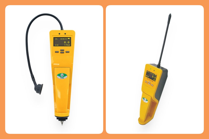
SF6 Gas Detector
| Product Information | Details |
|---|---|
| Product Model | PGAS-32 Type |
| Product Name | SF6 Infrared Leak Detector |
| Indication Error | < 2%F.S |
| Sampling Method | Pump Suction Type |
| Operating Temperature | (-10 to +60) °C |
| Response Time | (1 to 5) s |