Need Help: Providing Innovative and Sustainable Solutions.
Office Hours: 08:30am-6:00pm
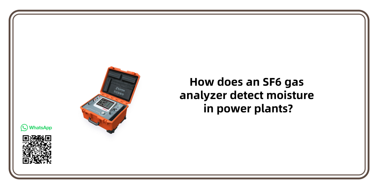
How does an SF6 gas analyzer detect moisture in power plants?
Date
2025-11-03
sale@sf6gasdetector.com
Website
www.sf6gasdetector.com
Get Solutions And Quotes
How does an SF6 gas analyzer detect moisture in power plants?
SF6 gas analyzers detect moisture in power plants primarily through three core technologies—electrolysis, chilled mirror, and laser absorption—each tailored to the on-site needs of power facilities, such as portability for field inspections or high precision for equipment maintenance. These methods target the trace water vapor in SF6 (typically measured in ppm, parts per million) to prevent insulation failure in high-voltage gear like GIS (Gas-Insulated Switchgear) or transformers.
1. Key Detection Technologies for Moisture in SF6 (Power Plant Scenarios)
Each technology works by converting moisture content into a measurable signal (e.g., electrical current, temperature, or light absorption), with tradeoffs in precision, speed, and portability—critical factors for power plant operations.
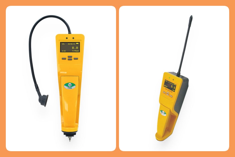
1.1 Electrolysis Method (Most Common for Portable On-Site Use)
This is the go-to choice for power plant technicians conducting routine SF6 moisture checks, as it balances portability and accuracy.
- Working Principle: The SF6 gas analyzer draws a controlled flow of SF6 gas through a moisture-sensitive electrolytic cell (filled with a porous material like phosphorus pentoxide, P₂O₅).
- Water vapor in the gas is adsorbed by the cell and electrolyzed into hydrogen (H₂) and oxygen (O₂) via an applied voltage.
- The electrolysis process generates an electrical current directly proportional to the moisture content in the gas (Faraday’s Law of Electrolysis).
- The SF6 analyzer converts this current into a ppm reading (e.g., 10 ppm = 10 mg/L of moisture).
- Power Plant Fit: Ideal for on-site testing of GIS, circuit breakers, or SF6 storage cylinders. Its compact design allows technicians to move between substations, and it provides real-time results (within 1–3 minutes) for quick maintenance decisions.
1.2 Chilled Mirror Method (High-Precision Calibration & Laboratory Use)
Power plants use this method for reference-level accuracy, such as calibrating portable analyzers or verifying critical equipment (e.g., new SF6-filled transformers).
- Working Principle: The SF6 gas analyzer cools a polished metal mirror (inside a sample chamber) at a controlled rate while flowing SF6 gas over it.
- As the mirror cools, moisture in the gas condenses into a thin film of dew or frost when the temperature reaches the dew point (the temperature at which air is saturated with water vapor).
- An optical sensor detects the first sign of condensation (by measuring light reflection changes from the mirror).
- The mirror’s temperature at this point (dew point temperature) is converted to moisture content (e.g., a dew point of -40°C corresponds to ~9 ppm moisture in SF6).
- Power Plant Fit: Used in on-site calibration labs or for pre-commissioning tests of high-voltage equipment. It delivers accuracy within ±0.1°C dew point, meeting strict IEC 60480 standards for SF6 gas quality.
1.3 Laser Absorption Method (Online Real-Time Monitoring)
For continuous moisture surveillance of critical SF6 equipment (e.g., 500kV+ GIS), power plants deploy online analyzers using this technology.
- Working Principle: The SF6 gas analyzer emits a specific wavelength of infrared (IR) laser (tuned to water vapor’s absorption spectrum) through a sample of SF6 gas.
- Moisture molecules in the gas absorb part of the laser light; the amount of absorption follows Beer-Lambert’s Law (more moisture = more light absorption).
- A detector measures the remaining light intensity, and the SF6 analyzer calculates moisture content in ppm.
- Power Plant Fit: Installed directly on SF6 equipment (e.g., GIS tanks) for 24/7 monitoring. It avoids manual sampling errors, triggers alerts for sudden moisture spikes (e.g., from seal leaks), and integrates with the plant’s SCADA system for centralized data management.
2. Step-by-Step Process for Moisture Detection in Power Plants
Power plant technicians follow a standardized workflow to ensure reliable results, regardless of the technology used:
- Gas Sampling: Extract a representative SF6 sample from the target equipment (e.g., GIS, circuit breaker) using a dry, clean sampling line (to avoid external moisture contamination).
- Pre-Treatment: Filter the sample to remove particulate matter, oil, or other impurities (common in power plant environments) that could damage the analyzer’s sensor.
- Detection: Pass the treated sample through the SF6 gas analyzer’s detection module (electrolytic cell, chilled mirror, or laser chamber) to measure moisture.
- Data Conversion: The analyzer converts the raw signal (current, temperature, or light absorption) into a moisture reading (ppm or dew point °C), displayed on the device or transmitted to a control system.
- Validation: Compare results against industry standards (e.g., IEC 60480 requires ≤50 ppm moisture for new SF6; ≤150 ppm for in-service equipment) to assess if the gas meets operational requirements.
3. Critical Considerations for Power Plant Use
To ensure accurate and safe moisture detection, power plants must address these factors:
- Calibration: Regularly calibrate analyzers (every 6–12 months) using certified SF6-moisture standard gases (e.g., 10 ppm, 50 ppm) to avoid drift in readings.
- Contamination Control: Use dry, oil-free sampling lines and purge the system with dry nitrogen before testing—moisture from ambient air or oil residues can skew results.
- Environmental Adaptation: Choose analyzers rated for power plant conditions (e.g., -20°C to 50°C operating temperature, dust/water resistance per IP54) to withstand substation or outdoor environments.
- Safety Compliance: Ensure the SF6 gas analyzer is explosion-proof (ATEX or IECEx certified) if used in hazardous areas (e.g., near high-voltage equipment) and follow OSHA/EU F-Gas rules for SF6 handling.
In summary, SF6 gas analyzers use electrolysis, chilled mirror, or laser technology to quantify moisture in power plants, with each method optimized for specific use cases (portable, precision, or online). By following proper sampling and calibration protocols, these tools help power plants maintain SF6 gas quality, prevent equipment failure, and comply with safety standards.
Realize The Recycling Of Sf6 Gas