SF6 Leak Detector: Find Leaks in GIS Flanges & Valves After Maintenance

Date
2026-11-09
[email protected]
Website
www.sf6gasdetector.com
Get Solutions And Quotes
Contact Factory
SF6 Leak Detector: Find Leaks in GIS Flanges & Valves After Maintenance
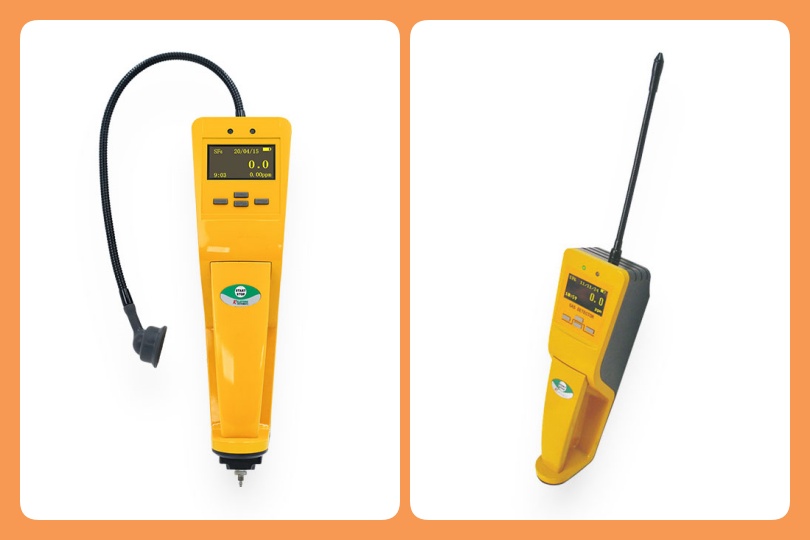
An SF6 leak detector for post-maintenance inspection of GIS flanges and valves helps maintenance teams identify localized gas leakage before gas-insulated switchgear returns to normal service. Disturbed flange seals, serviced valve assemblies, and refitted filling connections require particular attention after maintenance. A reliable inspection combines suitable detection sensitivity, controlled scanning, documented acceptance criteria, and safe gas-handling practices. The objective is not simply to obtain a low reading: it is to verify joint integrity under representative operating conditions and establish a traceable maintenance record.
Why GIS Flanges and Valves Need Targeted Inspection
GIS maintenance can introduce leakage through displaced O-rings, contaminated sealing faces, incorrect assembly, or damaged valve seats. Temperature changes and mechanical loading may also expose defects that are not evident immediately after reassembly.
Priority inspection points include:
- Flange circumferences and accessible gasket interfaces.
- Valve stems, bonnets, bodies, and service connections.
- Filling and recovery ports after equipment disconnection.
- Density-monitor connections and associated tubing.
- Newly installed blanking plugs and sealing caps.
A portable SF6 leak detector supports precise localization at these interfaces. However, it does not replace gas-density supervision, manufacturer-prescribed tightness testing, or formal leakage-rate assessment where required.
Selecting an SF6 Leak Detector for Post-Maintenance Inspection of GIS Flanges and Valves
Instrument selection should reflect the inspection environment, required acceptance method, and accessibility of the sealing surfaces—not simply the lowest advertised detection limit.
Compare Performance Using Defined Parameters
| Parameter | What to verify | Practical significance |
|---|---|---|
| Detection principle | Infrared, photoacoustic, or another validated technology | Influences selectivity and environmental response |
| Sensitivity | Stated minimum detectable concentration or leakage rate, with test conditions | Allows meaningful comparison |
| Response and recovery | Manufacturer-specified response, including sampling-line delay | Determines scanning speed and repeat-test timing |
| Measurement range | Resolution, saturation behavior, and alarm settings | Supports screening and localization |
| Sampling system | Probe geometry, hose length, pump status, and filter condition | Affects access and sample transport |
| Environmental limits | Temperature, humidity, ingress protection, and condensation restrictions | Establishes suitability for site conditions |
| Calibration | Documented calibration and functional-check procedure | Supports defensible inspection records |
Concentration and leakage rate are not interchangeable. A ppm reading indicates SF6 concentration in the sampled air. A leakage rate, such as grams per year, describes gas escaping over time. Converting between them requires a validated method with controlled sampling or collection conditions.
Evaluate Selectivity and Field Robustness
An SF6 leak detector should distinguish the target gas from likely background contaminants within its documented capabilities. Review cross-sensitivity data rather than assuming any sensing technology is interference-free.
For outdoor GIS inspections, wind can dilute escaping gas. Indoors, residual SF6 from recent handling may raise background levels. Both conditions affect interpretation and may require ventilation, delayed retesting, or an approved localized collection technique.
A Practical Post-Maintenance Inspection Workflow
1. Establish Safe, Representative Conditions
Follow the site permit-to-work procedure and the GIS manufacturer’s maintenance instructions. Confirm equipment status, electrical clearances, compartment identification, and gas pressure or density conditions required for testing.
Use adequate ventilation and assess confined-space hazards. SF6 can displace oxygen, while gas exposed to electrical arcing may contain hazardous decomposition products. Apply the specified personal protective equipment and gas-handling controls; a leak detector is not an oxygen monitor.
2. Check the Instrument Before Scanning
Inspect the probe, tubing, filters, battery, and pump. Allow the prescribed warm-up period, establish a baseline in suitable clean air, and perform the manufacturer-recommended functional check.
Use a traceable reference leak or appropriate test source where specified. Record the instrument identification and calibration status. Zeroing in contaminated air can mask leakage and should be avoided.
3. Scan Each Interface Systematically
Move the probe slowly around the full accessible flange circumference and every relevant valve interface. Maintain the manufacturer-recommended probe distance and account for sampling-line delay.
Avoid touching sealing surfaces with the probe. At complex valve assemblies, inspect individual connections separately to distinguish the source from gas migrating nearby.
4. Confirm and Document Suspected Leaks
When the SF6 leak detector responds, withdraw the probe to background air and allow recovery. Repeat the approach to check whether the signal is reproducible and localized.
If background contamination prevents reliable interpretation, correct the conditions before accepting the result. After repair, repeat the inspection under the specified test conditions. Do not tighten pressurized assemblies unless the manufacturer’s approved procedure explicitly permits it.
Scenario-Based Inspection Solutions
Flange Reassembled After Internal Maintenance
Inspect the complete sealing perimeter after the required stabilization period. If access is restricted, use an approved extension probe or alternative validated test arrangement. Document inaccessible areas rather than reporting the entire flange as inspected.
Valve Leaks After Gas-Handling Equipment Removal
Check the service-port closure, valve stem, and connection interfaces separately. A temporary hose connection may have obscured leakage during filling. Repeat testing with final caps and closures installed as specified.
Elevated Background Following Gas Recovery
Ventilate safely and re-establish a representative baseline. Do not interpret a widespread elevated reading as evidence that every joint leaks, or adjust the alarm merely to suppress the indication.
Standards, Compliance, and Acceptance Criteria
Relevant references include IEC 62271-203 for GIS above 52 kV and IEC 62271-4 for handling gases used for insulation or switching. IEC 60376 addresses technical-grade SF6 quality, while IEC 60480 addresses reuse specifications; neither is a handheld detector certification.
Verify locally applicable environmental legislation. In the European Union, Regulation (EU) 2024/573 establishes fluorinated-greenhouse-gas obligations, with requirements depending on equipment and activity.
ISO/IEC 17025-accredited calibration can strengthen measurement traceability when the calibration falls within the laboratory’s accredited scope. It does not independently certify detector suitability.
Frequently Asked Questions
Does a zero reading prove that GIS is leak-free?
No. It means no signal was detected above the instrument’s capability under the inspection conditions. Background, access, wind, and scanning technique affect results.
What is an acceptable leak-detector reading?
There is no universal handheld concentration threshold for all GIS. Use the manufacturer’s procedure, contractual requirements, and applicable standards.
How often should the detector be calibrated?
Follow the manufacturer’s interval and the organization’s quality system. Damage, failed checks, or suspect results may require earlier calibration.
A Defensible Return-to-Service Decision
Using an SF6 leak detector for post-maintenance inspection of GIS flanges and valves is most effective when results are repeatable, conditions are recorded, and acceptance criteria are established beforehand. Document repairs, retests, limitations, and responsible personnel to support an auditable return-to-service decision.